Preparation and characterization of the waterproof PDG-Mg electrode
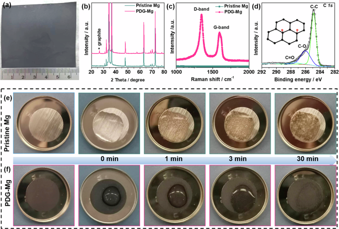
Figure 2a shows the optical image of metallic Mg foil after modification by simply drawing a graphite-based interface layer with a pencil. Benefiting from the solvent-free transfer of the PDG interphase from the pencil to the Mg foil, a large size (6.5 × 6 cm2) of PDG-Mg foil can be obtained, holding great promise for large-scale production to meet industrial demands. Considering the homogeneity of microstructure and the efficient protection for Mg metal substrate (Fig. S1), the optimal PDG interphase layer has a mass loading of 0.2 mg cm−2. To investigate the structural properties of PDG interphase, X-ray diffraction (XRD), Raman spectroscopy, and X-ray photoelectron spectroscopy (XPS) measurements were performed. Compared with the pristine Mg, the PDG-Mg electrode exhibits an additional peak at 26.4° in the XRD pattern (Fig. 2b), which corresponds to the (002) plane of graphite32,33,34. The graphitic nature of the PDG interphase is further substantiated through Raman spectroscopy, as shown in Fig. 2c, which reveals characteristic peaks corresponding to the D and G bands at approximately 1350 and 1580 cm−1, respectively. Notably, the intensity of the D-band surpasses that of the G-band, indicative of the high degree of disorder within the PDG structure, stemming from the exfoliation of pencil lead during the drawing process32. As observed from the XPS survey spectrum (Fig. S2a), the main elements in the PDG layer are C, O, and Si, respectively. The minimal Si signal (Fig. S2d) likely originates from the SiO2 clay added during the pencil-lead manufacturing procedure33. In the high-resolution C 1 s spectrum (Fig. 2d), three deconvoluted peaks at 284.6, 286.0, and 287.6 eV correspond to graphite C, -C-O, and -C = O groups, respectively. These O-containing groups are also evident in the O 1 s spectrum (Fig. S2c) and often play a pivotal role in improving the surface metallophilicity of carbon-based materials35.
Visualizing water-induced Mg passivation and its inhibition by PDG interphase
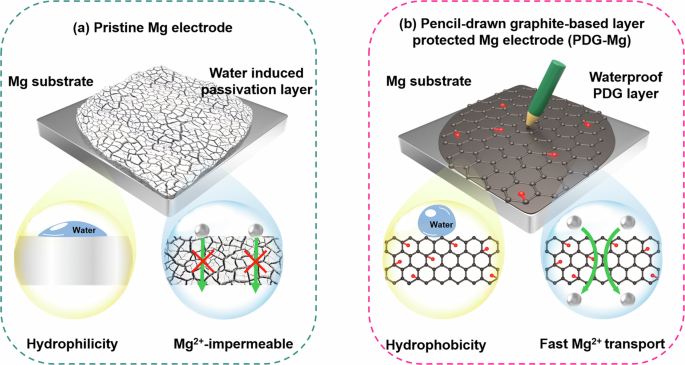
After successfully synthesizing the PDG interphase, our initial experimental investigation focused on assessing its effectiveness in mitigating water intrusion onto the underlying Mg metal. Figure 2e, f provide a series of time-lapse optical images depicting the behavior of pristine Mg and PDG-Mg electrodes upon adding a droplet (30 μL) of water to their surfaces. Upon contact with water, the pristine Mg electrode rapidly becomes wetted, showcasing its inherent hydrophilic nature. Simultaneously, some bubbles are visible on the pristine Mg electrode attributed to the hydrogen evolution reaction. Along with gas evolution, pristine Mg foil begins to lose its metallic luster after 1 min of water treatment. As the water treatment progresses, the surface of the pristine Mg electrode ultimately transitions into an uneven greyish-white appearance, signifying substantial electrode passivation. In stark contrast, when water droplets contact the surface of the PDG-Mg electrode, they exhibit minimal spreading, and no bubbles are generated throughout the entire water treatment process. This waterproof behavior can be attributed to the distinctive characteristics of the PDG interphase, which not only affords hydrophobicity to suppress the spreading of water droplets, but also serves as a shield, preventing water from permeating through and initiating detrimental side reactions with the underlying Mg substrates.
Identification of the chemical composition of water-induced passivation layer
To investigate the structural changes occurring on the surfaces of both pristine Mg and PDG-Mg electrodes during water treatment, we employed scanning electron microscopy (SEM) and energy-dispersive X-ray spectroscopy (EDX). In Fig. 3a, b, it is evident that the pristine Mg electrode undergoes a transformation from a smooth surface to one that is porous and rough following water treatment. Additionally, the EDX spectrum reveals a notable increase in the presence of O element (Fig. S3). These observations provide compelling evidence of severe passivation affecting the pristine Mg electrode, a conclusion corroborated by the appearance of peaks corresponding to Mg(OH)2 and MgO in the XPS spectra and XRD patterns (Fig. S4)17. To accuratly identify the chemical components and their spatial distribution within the water-induced passivation layer, TOF-SIMS and Raman measurements were further performed on pristine Mg after the water treatment. As displayed in Fig. 3c, Fig. S9, ion fragments of MgOH–, MgO–, and MgH– are detected at the mass-to-charge ratio (m/z) = 40.988, 30.978, and 24.995, respectively, which can be attributed to Mg(OH)2, MgO, and MgH2 products. In particular, the signal intensity of MgH– is approximately an order of magnitude weaker than that of MgOH– and MgO–, which might explain why previous studies did not detect MgH2, potentially leading to its oversight. From the depth profile of the pristine Mg electrode after 30 mins of water treatment (Fig. 3d), we also observed an intensity peak of MgH– at a depth of approximately 50 nm, providing solid evidence for the existence of MgH2. In addition, the MgO– signal remains detectable throughout the entire etching process, indicating that the thickness of the passivation layer likely exceeds 1 μm. 3D reconstructions of these detected signals were further provided to gain further insight into the microstructure of the passivation layer (Fig. 3d). It can be clearly observed that MgOH– and MgO– are densely concentrated within the outermost 100 nm and 300 nm, respectively, while the MgH– signal is sparsely distributed throughout the passivation layer. The Raman spectra of the water-treated pristine Mg electrode (Fig. S10b) also exhibits characteristic MgO bands at 278 and 445 cm−1[,36, MgH2 band at 311 cm−1,31, and Mg(OH)2 bands at 725 and 810 cm−1,37, which again evidence the co-existence of MgH2, Mg(OH)2, and MgO in the water-induced passivation layer on metallic Mg. It’s also worth noting that no MgH2 signal can be detected from the pristine Mg foil before use and after 30 min of air exposure (Fig. S10), which in turn illustrates that the formed MgH2 originates from the side reactions with Mg and H2O during the water treatment (see Eqs. (1)–(3)).
a, b SEM images and (c) TOF-SIMS spectra of MgOH–, MgO–, and MgH– ion obtained from pristine Mg electrode before and after 30 mins of the water treatment. d TOF-SIMS depth profiles and 3D render images of MgOH–, MgO–, and MgH– for pristine Mg electrodes after 30 min of the water treatment. e, f SEM images and (g) TOF-SIMS spectra of MgOH–, MgO–, and MgH– ion obtained from PDG-Mg electrode before and after the water treatment. h TOF-SIMS depth profiles and 3D render images of MgOH–, MgO–, and MgH– for PDG-Mg electrodes after 30 min of the water treatment.
Prior to water treatment, the surface of the PDG-Mg electrode exhibits a relatively rough texture, featuring the distribution of numerous flakes, as depicted in Fig. 3e and Fig. S7a. A closer examination using transmission electron microscopy (Fig. S7b) reveals that these flakes have dimensions on the order of several hundred nanometers, displaying the characteristic two-dimensional structure associated with multilayer graphite32,33. A cross-sectional view (Fig. S7c, d) highlights the close connection between the PDG interface layer and the underlying Mg substrate, with the thickness of the PDG interphase measuring approximately 1 μm. Under the protective shield of this PDG interphase, the PDG-Mg electrode showed minimal changes in the surface morphologies after the same water treatment (Fig. 3f). The compositional features of PDG-Mg electrode before and after the water treatment was further compared by the results of TOF-SIMS, EDX, XPS, XRD, and Raman spectroscopy, as displayed in Fig. 3g, h, and Fig. S8–10. It can be clearly observed that the graphitic nature of the PDG interphase remains almost unchanged except for a slight increase in the O signal, which should comes from the MgO and Mg(OH)2 that forms during the water treatment. More importantly, the water-induced by-product, MgH2, is undetectable from the PDG-Mg electrode during the whole water treatment process. Based on above comprehensive characterisations, it can be validated that the side reactions between Mg and water is greatly prevented with the protection of the PDG interphase.
Probing the working mechanism of the passivation layer and the PDG interphase
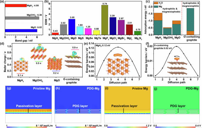
After identifying the chemical components within the water-induced passivation layer, we conducted first-principles calculations to understand their effects on the interfacial kinetics and stability of the Mg metal anode. As exhibited in Fig. 4a, the band gap of MgH2, Mg(OH)2, and MgO is calculated to be 4.05, 6.38, and 6.02 eV, respectively. The lower band gap of MgH2 suggests that MgH2 formed in the passivation layer can increase the electron tunneling probability from the Mg metal substrates to the electrolytes, thus promoting further side reactions between them36,37. Additionally, MgH2 also exhibits a significantly lower electrochemical stability window (ESW, 0.43 V, Fig. 4b) compared to Mg(OH)2 (2.02 V), MgO (3.05 V), and other magnesium compounds (0.75–5.74 V). These results further underscore that the existence of MgH2 in the passivation layer may adversely affect the stability of the electrode/electrolyte interface.
The comparison of (a) band gap and (b) electrochemical stability window of MgH2 with Mg(OH)2 and MgO. c DFT adsorption energies of H2O molecules and Mg adatoms on MgH2(001), Mg(OH)2(001), MgO(001), and O-containing graphite. d Charge density difference plots, and Bader charge of Mg adatom on Mg(OH)2(001), MgO(001), MgH2(001), and O-containing graphite. Blue and yellow spheres indicate charge depletion and accumulation regions, respectively. The calculated Mg diffusion energy barrier on (e) MgH2 and (f) O-containing graphite. The orange, red, and brown balls denote Mg, O, and C elements, respectively. COMSOL simulation of the distribution of (g, h) Mg2+ concentration and (i, j) electric field over the Mg anode surface with (g, i) the passivation layer and (h, j) the PDG interphase at a current density of 1 mA cm−2.
Density functional theory (DFT) calculations were further applied to delve deeper into the interactions between the passivation layer and H2O molecules or Mg atoms. The adsorption models on the surfaces of MgH2(001), Mg(OH)2(001), and MgO(001) were summarized in Fig. S11, S12. It can be seen from Fig. 4c that the adsorption energy of H2O is greater than that of Mg on all the surfaces: MgH2 (−1.03 eV for H2O vs. −0.50 eV for Mg), Mg(OH)2 (−0.48 eV for H2O vs. −0.47 eV for Mg), and MgO (−0.77 eV for H2O vs. −0.52 eV for Mg). These values indicate the hydrophilic and magnesiophobic properties of the passivation layer, which is likely to induce an H2O-rich and Mg2+-poor region in the vicinity of electrode, seriously exacerbating further side reactions between passivated Mg anode and aqueous solutions. Conversely, the O-containing graphite in the PDG layer exhibits a much stronger interaction with Mg adatom (−1.62 eV) as compared to H2O (−0.28 eV), which favors the establishment of a region of Mg enrichment and H2O depletion near the PDG-Mg anode, thus allowing reversible Mg plating/stripping behavior in liquid electrolytes, including aqueous solutions.
Figure 4d visualizes the differential charge density of the most stable configurations for MgH2, Mg(OH)2, MgO, and O-containing graphite with Mg adatoms adsorption. The electron of the adsorbed Mg atom on the O-containing surface groups of the PDG layer is more delocalized, contributing to the stronger interfacial interactions between them. Furthermore, as revealed by Bader charge, the electron donation of Mg to O-containing graphite reaches 0.9 e, much higher than those of MgH2 (0.1 e), Mg(OH)2 (0.5 e), and MgO (0.2 e), suggesting a stronger magnesium affinity of PDG interphase. Together with its metallic-like conductivity34, PDG interphase plays a crucial role in alleviating Mg depletion and mitigating voltage hysteresis during Mg electroplating.
In addition to its hydrophobic and magnesiophilic properties, the PDG interphase is also conducive to facilitating Mg ion transport, a critical factor for the success of a Mg protective layer. Utilizing the climbing-image nudged elastic band (CI-NEB) method, we have calculated that the energy barrier for Mg diffusion on the O-containing graphite is exceptionally low, measuring just 0.02 eV (Fig. 4e). This value stands in stark contrast to the higher barriers observed for MgH2 (0.17 eV, Fig. 4f), MgO (0.2 eV, Fig. S13a), and Mg(OH)2 (0.03 eV, Fig. S13b), clearly indicating a significantly faster Mg transport through the PDG interphase compared to conventional passivation layers. Furthermore, the confined liquid electrolyte in the gaps between the pencil-drawn graphite sheets also allows rapid Mg transportation on the PDG-Mg surface. Benefiting from the dual enhancement of Mg-transfer capability and magnesiophilicity by the PDG interphase, the Mg electroplating behavior on the anode surface is expected to be significantly improved.
To validate our previous hypothesis, we conducted simulations of ion flux distribution and electric field across the Mg anode surface using finite element simulations through COMSOL Multiphysics38,39. The simulation models (Fig. S14) were built by introducing a compact passivation layer and stacked graphite flakes onto the surfaces of pristine Mg and PDG-Mg electrodes, respectively. Due to the inherent poor affinity of Mg and the substantial diffusion barrier for Mg ions, the concentration of Mg2+ ions near the passivated surface of pristine Mg electrode can be observed to be notably lower than that in the bulk electrolyte (Fig. 4g, Fig. S15). This marked concentration polarization at the Mg/electrolyte interface enhances the surrounding electric field intensity, as depicted in Fig. 4i. Consequently, it leads to a significant increase in overpotential and diminished reversibility during Mg plating and stripping. Encouragingly, with the introduction of the PDG surface layer, we witnessed a substantial enhancement in Mg2+ concentration, soaring from 1.55 to 480 mol m−3 (Fig. 4h, Fig. S15). Simultaneously, there was a sharp reduction in overpotential, declining from 1.05 to 0.20 V (Fig. 4j). Most importantly, the presence of the PDG interphase led to the uniformization of both the Mg2+ flux and the electric field at the electrode/electrolyte interface, accounting for achieving highly reversible and low-barrier Mg plating.
Electrochemical performance of the PDG-Mg electrodes after the water treatment
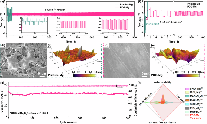
To assess the practicality of the waterproof PDG-Mg electrodes, we conducted galvanostatic cycling tests on symmetric cells employing PDG-Mg electrodes following water treatment (achieved by adding 30 μL of water to their surfaces). 0.3 M Mg(OTf)2 and 0.2 M MgCl2 in DME was chosen as the electrolyte, as this conventional non-nucleophilic electrolyte is highly compatible with Mg metal electrodes40,41,42. As exhibited in Fig. 5a, the symmetric cell utilizing water-treated pristine Mg anodes initially exhibits pronounced oscillations in the voltage curves, suggesting the deactivation of the pristine Mg electrode due to passivation reactions induced by contact with water. In contrast, the symmetric cell employing the water-treated PDG-Mg electrode demonstrates stable Mg plating/stripping cycling over 900 h at 1.0 mA cm−2 and 1.0 mA h cm−2. This endurance implies that the electrochemical activity and stability of PDG-Mg electrodes remain unaffected during the water treatment. Upon closer examination of the enlarged voltage curves, it can be found that the overpotential remains at approximately 200 mV after the first activation cycle and only experiences a slight increase to approximately 250 mV after 900 h of continuous cycling. This consistent, small, and stable overpotential observed in the waterproof PDG-Mg electrode serves as compelling evidence of the uniqueness of the PDG interphase and its vital role in expediting Mg2+ transfer to the Mg anode surface and stabilizing the Mg/electrolyte interface.
a Galvanostatic voltage curves of symmetric cells with water-treated pristine Mg or PDG-Mg electrodes in a conventional non-nucleophilic electrolyte at 1.0 mA cm−2 and 1.0 mAh cm−2 (b, d) SEM and (c, e) AFM images of water-treated pristine Mg or PDG-Mg electrodes resulted from the symmetric cells after 10 cycles at 1.0 mA cm−2 and 1.0 mAh cm−2. f Galvanostatic voltage curves of symmetric cells with water-treated pristine Mg or PDG-Mg electrodes in a conventional non-nucleophilic electrolyte at 3.0 mA cm−2 and 3.0 mAh cm−2. g Cycling performance of water-treated PDG-Mg | |Mo6S8 full cell. h Comparison of our PDG interphase with other reported artificial interphases as summarized in Table S1.
Post-mortem SEM, atomic force microscopy (AFM), and XPS investigations were applied to gain further insights into the surface morphology and chemistry of water-treated pristine Mg and PDG-Mg electrodes after cycling in symmetric cells. The SEM image in Fig. 5b suggests that the cycled pristine Mg electrode exhibits a highly porous surface structure with numerous cracks randomly distributed across its surface. Furthermore, an observed height difference of approximately 0.8 μm from the AFM image (Fig. 5c) indicates the accumulation of a substantial number of by-products on the pristine Mg electrode during cycling. Conversely, the PDG-Mg electrode, after 10 cycles, presents a relatively flat and densely packed surface with a height difference of only about 0.35 μm (Fig. 5d, e). Even after cycling for 50 plating/stripping cycles (Fig. S16, 17), the PDG interphase maintains its structural integrity, as evidenced by the presence of C and Si elements in the EDX mappings. From the results of XPS spectra (Fig. S18), the relative intensities of the MgO, Mg(OH)2, and MgF2 of the PDG-Mg is significantly lower compared with those of the pristine Mg, and the formation of MgCO3, which is poor in Mg2+ transport40, is also eliminated. We also note a distinct peak related to metallic Mg (49.4 eV) in the Mg 2p XPS spectrum of cycled PDG-Mg electrode41,42, which further suggests that the PDG-layer can suppress electrolyte decomposition, thus contributing to low interfacial resistance (Fig. S19) for rapid Mg2+ electroplating and stripping.
When the cycling current density and areal capacity are raised to 3.0 mA cm−2 and 3.0 mAh cm−2 (Fig. 5f, Fig. S20), the water-treated Mg | |Mg symmetric cell could not run at all. As a comparison, with the PDG interphase protection, stable electrochemical Mg plating/stripping for more than 400 h can be achieved in the water-treated PDG-Mg | |PDG-Mg symmetric cell. Furthermore, the water-treated PDG-Mg can also steadily run at a current density up to 5.0 mA cm−2 (Fig. S21), indicative of its promising rate capability. To meet the practical requirement, we assembled the full Mg-metal cells using a Chevrel phase Mo6S8 cathode to pair with the water-treated PDG-Mg electrode. At a current density of 0.5 C (Fig. 5g), the full cell affords an initial capacity of 47.2 mAh g−1, which remains at 42.1 mAh g−1 after 500 cycles, corresponding to a capacity retention of 89.2%. Such cycling stability is comparable to that of the full cell utilizing an untreated Mg anode, which achieved a capacity retention of 92.3% after 500 cycles at 0.5 C, as shown in Fig. S22. These results provide solid evidence that the PDG interphase effectively inhibits water-induced passivation and deterioration of the metallic Mg anode. It’s also worth noting that the fluctuations in capacity from temperature variation during long-term battery cycling are highly reproducible (Fig. S23) and have been widely observed in literature7,39,43. The practicality of the waterproof PDG-Mg electrode was further validated in a 5 M MgCl2 aqueous electrolyte. As illustrated in Fig. S24a, the symmetric cell using PDG-Mg electrodes exhibits long-term stability over 100 h, significantly outperforming its pristine Mg counterpart. Moreover, the PDG-Mg | |Mo6S8 full cell also achieves relatively stable cycling performance (Fig. S24b).
To put this work in a historical perspective, we summarized the previous efforts of constructing artificial interface layers for enabling reversible Mg-metal anode chemistry (Fig. 5h). A notable example is that Ban et al. engineered a thermal-cyclized polyacrylonitrile (cPAN)-based polymeric layer on the Mg powder surface, which enabled the reversible cycling of a high-voltage Mg metal battery with a vanadium pentoxide cathode in the water-containing, carbonate-based electrolyte22. Inspired by this work, many other Mg2+ conductive layers have been artificially achieved by metal-organic framework coating44, and inorganic or organic organohalogen compounds modification23,38,42,45,46. However, the effectiveness of these artificial layers against the water instability of the Mg metal anode remains unexplored. Moreover, the PDG-Mg electrode without water treatment is also capable of cycling stably in Mg(OTf)2-MgCl2-DME electrolyte with H2O addtives (Fig. S24), and even in a chloride-free magnesium bis(trifluoromethanesulfonimide) (Mg(TFSI)2)-DME electrolyte (Fig. S26), showcasing the advantages of PDG interphase in realizing reversible Mg-metal anode chemistry. Taking other factors into consideration, listed in Table S1, including low cost, electrode size, and solvent-free synthesis of PDG interphase, it is reasonable to expect that our PDG-Mg electrode holds great promise toward the development of affordable and practical Mg metal batteries.


